
What Does a Speed Sensor in the Motor Spindle Do?
The primary function of speed sensors is the precise measurement of spindle speed. SPINOGY motor spindles offer various configuration options for speed sensors. In principle, the following sensor types are available:
- Inductive speed sensor
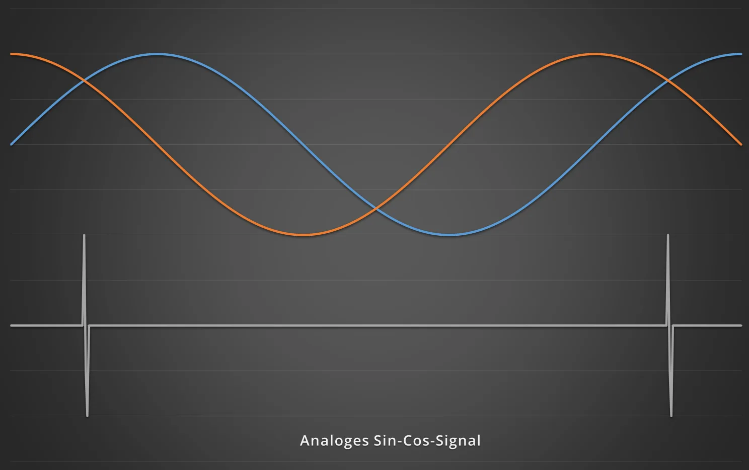
- Analog encoder (sin/cos)
- Digital encoder (TTL)
The inductive sensor is based – as the name suggests – on an inductive measuring principle, whereas encoders operate on the magnetoresistive measuring principle. Regardless of the measuring principle, all sensors detect the teeth of a rotating pole wheel. Each detected tooth generates a pulse.
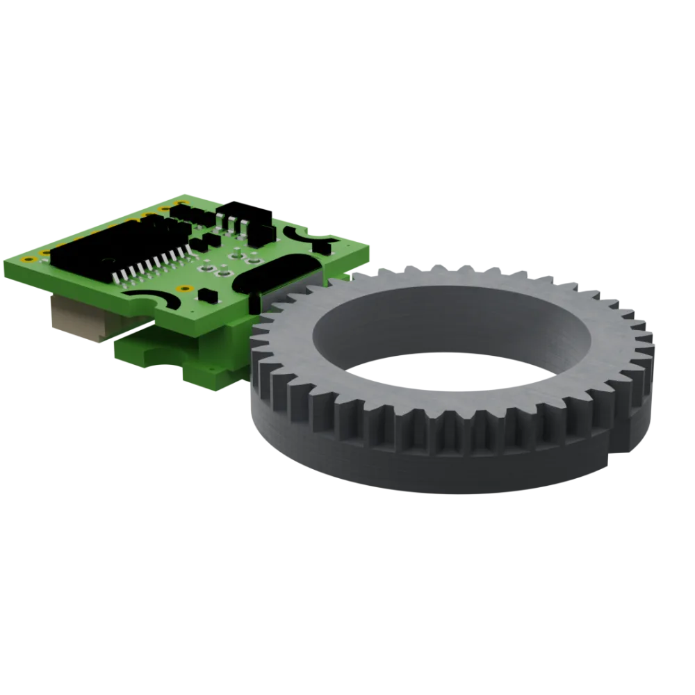
Evaluation electronics (e.g. a frequency inverter) count these pulses per revolution. Combined with the known number of teeth on the pole wheel, this makes it possible to calculate the actual speed of the spindle.
This signal can then be used in the inverter for closed-loop control. The actual speed is continuously compared with the target speed. If the speed drops – for example due to a higher machining load – the inverter automatically compensates in order to keep the desired speed constant.
A decisive advantage of this control:
The maximum torque can be delivered even in the range from 0 to 5,000 rpm.
Inductive sensor or encoder?
In a simple and cost-effective version, this speed control can already be implemented with an inductive speed sensor.
For more demanding applications, however, we recommend using an encoder. It offers a significantly higher resolution and thus enables more precise control of the spindle speed.
Another advantage: the encoder makes it possible to determine the position of the spindle shaft exactly, since considerably more position signals are captured per revolution.
In a “simple” version, this can be achieved with the inductive speed sensor; for high-end users, we recommend using the encoder. It offers considerably more functions and has a better resolution, which results in better controllability.
Rigid Tapping – Thread cutting without a compensating chuck
Using an encoder enables “Rigid Tapping” and is therefore easily possible with SPINOGY motor spindles. But what exactly is it:
Rigid tapping is a CNC thread-cutting process in which the tap is clamped directly in the tool holder without a compensating chuck.
The movement of the Z-axis is synchronized exactly with the speed of the spindle.
Advantages of rigid tapping:
- No compensating chuck required
- Lower costs and higher precision
- Reduced risk of tap breakage
- Faster machining cycles
Technical requirements:
- Complete synchronization of spindle speed and feed axis
- Precise position monitoring of the spindle shaft